
|
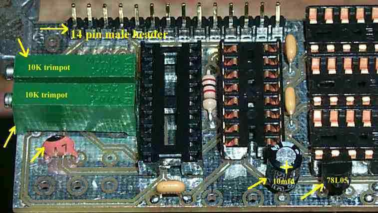
Be careful to get the correct header (male) installed. Check picture carefully. If you make a mistake, installing the female header instead, do not try to fix it. There is no way you will unsolder the header and remove it. I tried! In reality, it doesn't matter which header is installed, works both ways. Arrows point to the other five components that you solder on the board at this time. Please note that the + side of the electrolytic is facing down toward the edge of the PCB. The 22pf cap as noted in the instructions may be a different value. As shown in this picture, a 47pf cap was supplied in the kit. The different value cap should not make a difference in performance. |
|
|
|
|
Send E-Mail || Amateur Radio Receivers || Electroluminescent Receiver || Back to DFD2 Instructions