
|
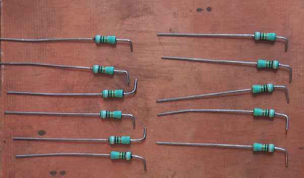
The PCB ground plane above is about 2" by 4" and the resistors are approximately 10 megohm. The 11 resistors are used for standoffs in building the circuit. The circuit can be built on a smaller piece of PCB, but I used a large piece to help clarify the building process. Bend one lead as shown and cut. The bend in the lead gives a much better solder joint than just sticking one end into a pool of solder. |
|
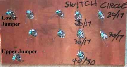
Picture shows the location of where the standoffs should be soldered. Label the jumper, switch and circle connections now before parts get in the way. |

|
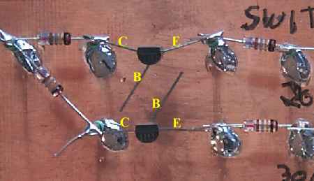
Please note the location of the black bands on the diodes. These diodes were used because the black bands were clearly seen. The ones in the kit are 1N914/1N4148s which are smaller than the ones shown in the picture. Picture shows all the diodes with the leads cut. On the left where two diodes come together, solder the leads where only one lead goes, then solder the two leads on it's standoff. Just be sure when you solder you don't knock one off because the other end is not soldered. I like to leave the standoff's extra lead length on the resistor because they provide a heat sink to help cool the solder down and prevent damage to the parts being soldered. |
|
Solder the two transistors next. Notice which way the flats of the transistors are positioned. Toward the top of the board. The collectors of the NPN 2N3904 are on the left, emitters on the right, and the base wires at an angle. Position as above and the resistors will be easy to solder. |
|
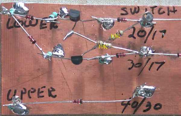
The two 10K resistors are soldered to the base leads of the transistors and after the first diode where the switch connections are made. |

|
Loops are made by winding down the leads of the standoff resistors (with a pair of needle nose pliers) where connections are going to be made to the circuit. Four standoff resistor leads are cut. The ones on each side of the transistors at the collector and emitter leads. |
|
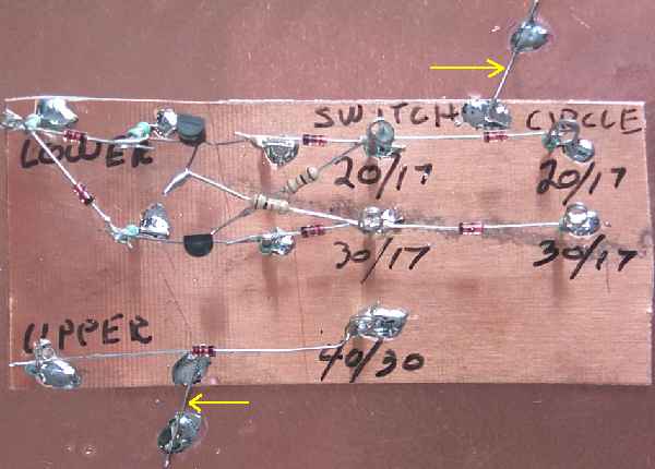
Use two cut resistor leads to hold down the board behind the frequency counter. Yellow arrows show the hold down leads. The frequency counter is not shown, but the board is placed directly behind the counter. |
|
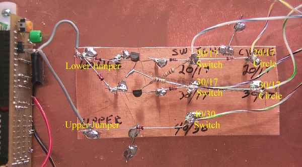
Wires are soldered to the connection points and soldered. Make sure you use plenty of lead length so the boards can be laid apart for diagnosis, testing and experimenting. Approximate lead length of the wires to the jumpers are 1 3/4" and the leads to Board 1 are 16". Twist the five wires together in the middle 10" and secure with a couple of plastic tie wraps to make a cable. This will keep them from flopping all over the place. |
|
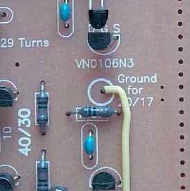
The connection on Board 1 for the 20/17 Bandpass Filter connection circle. |
|
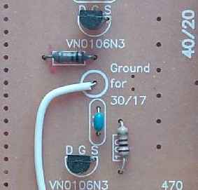
The connection on Board 1 for the 30/17 Crystal Filter connection circle. |

|
The yellow arrows point to the connections that are used at the band switches. The yellow boxes enclose the labeling and the holes that are used to solder the connections. The switches will already be installed by the time you install these wires. If the wires from the circles directly to these switches were installed during "Mounting/Testing Board 1" instructions, take them off as they will prevent the automatic switching from working. Back to Automatic Switching with the Board 1 Switches |
Send E-Mail || Amateur Radio Receivers || Electroluminescent Receiver || Back to DFD2 Instructions